上海驿劲电气设备制造有限公司

全国统一客服热线:13868728093

产品中心

当前位置: 首页 > 产品中心 > 户内高压负荷开关 > FN3-12

FN3-12

详细信息

概述

Summary

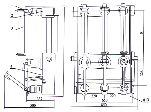
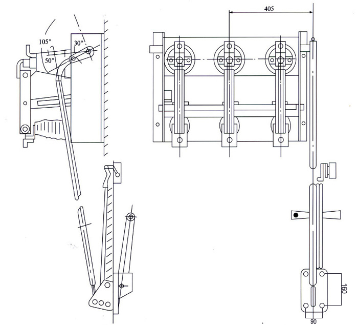
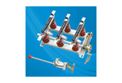
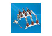
1、FN3-12、FN3-12R、FN3-12R/S负荷开关系户内装置的高压电器。适用于交流50Hz、6KV或12KV的网络中,作为开断和闭合负荷及过荷电流之用,亦可用作开断和闭合空载长线。空载变压器及电容之开关。带有RN3型熔断型的负荷开关(FN3-12、FN3-12R/S)可切断路器,作保护开关之用。

2、本负荷开关可配用CS3型及CS2型手动操作机构进行操作。

1、FN3-12、FN3-12R、FN3-12R/S Series are used in the network of AC 50Hz、6KV or 12KV for breaking or closing load and over-load current. they are also used in breaking and closing no-loading . The switch or no-load transformer and capacitor with KN3 type fuse box. Can cut off short-circuit for protecting switch.

2、They can be equipped with CS3 type and CS2 type handle operating mechanism.

工作条件

Serviec Condition

1、海拔不超过1000米;
2、周围空气温度不高于+40oC及不低于-10oC;
3、空气相对湿度不大于90%的户内场(当温度为+25);
4、无导电性尘埃的环境中;
5、无破坏金属和绝缘的腐蚀性气体的物体;
6、无剧烈震动和冲击的地方;
7、无燃烧与爆炸危险的环境中。
1 、The altitude does not exceed 1000m.
2、The ambient air temperatrue : Max:+40oC. Min:-10oC.
3、The relatire humidity of air not bigger 90% (temperature:25oC)
4、The working situation have no conductivity dust.
5、The working situation have no corrosive gas of effect insulation anddestroy metal.
6、The working situation without violent vibration and striking.
7、The working situation have no explosive danger and fire.

技术参数

Technical parameter

1、负荷开关的基本技术数据应符合下表的规定:

The load switch is suitable for the basic technical parameter (please see the table)

型号

Type

额定电压(KV)

Rated voltage

工作电压(上限)(KV)

Max.working voltage

额定电流(A)

Rated current

动稳定电流(KA)

Machine stabling current

热稳定电流(kA/s)

Heat-stabling current

FN3-12 12 12 400 25 10/2

2、负荷开关所配带的熔断器的型号及数据应符合下表的规定:

The load switch witch fuse box is suitable for the technical parameter (please see the table)

型号

Type

额定电压(KV)

Rated voltage

额定电流(A)

Rated current

开断电流(上限)
(有效值)(KA)

Max.breaking
current(value)

断流电容量(上限)

Max.cut-off capacity

当切断极限短路时
电流之上限峰值(KA/s)

Current peak when cutting
off limit short-circuit

FN3-3 3 10~50 40 200 24.5
75~100 24.5
200 35
FN3-6 6 10~50 20 200 14
75 14
100 19
200 25
FN3-10 12   12 200  
10~50 8.6
75 8.6
100~50 15.5

外形图

Appearance diagram

1、拐臂
2、框架
3、上绝缘子
4、主静触头
5、弧动触头
6、闸刀
7、绝缘拉杆
8、下触座
9、下绝缘子
10、熔断器

1、Bend the arm
2、Framework
3、Upper insulator
4、Main static contact
5、Arc moving contact
6、Switch
7、Insualting pole
8、Lower insulator
9、Lower insulator
10、Fuse box

FN3-12、FN3-12R 型负荷开关

FN3-12、FN3-12R Type Load Switch


1、插座
2、框架
3、熔断器
4、负荷开关本体

1、Socket
2、Framework
3、Fuse Link
4、Load switch body

FN3-12R/S 型负荷开关

FN3-12R/S Type Load Switch


安装图

Installation diagram

1、FN3-12负荷开关与CS3操动机构传动装置连接安装图(机构安装在开关之后)

Installation diagram for connecting FN3-12 Load Switch with CS3 operating mechanism friving (The mechanism is installed at the back or the switch).

产品样本
电子样本

下一个:FN3-12

返回列表